Cross section 2
Let’s consider a cross section (See examples/matrix/cross_section_2)

Cross section
We can use Matrix class to create this type of
geometry. First we need to decompose geometry into blocks and then modify each of
them according to the dimensions.
Decomposition
Geometry could be decomposed into 4 blocks: BOTTOM, TOP1, TOP2 and TOP3,
where TOP3 part is required for a small surface with \(F\), \(u_v\)
boundary condition at the end of the upper part of the geometry. Without the boundary
condition, 3 blocks would be enough. Each of these blocks will be described by
Matrix class.

Decomposition of geometry
Geometry
Let’s define that X-axis is directed to the right, Y - in the depth and Z - upward, i.e cross section is symmetric along Y-axis.
First we should create a separate file for each of the blocks:
top_1.yaml
1 data:
2   class: block.Matrix
3   matrix: [ [ 0, 0.250 ], [ 0, 1 ], [ 0, 0.250 ] ]
top_2.yaml
1  data:
2    class: block.Matrix
3    matrix: [ [ 0, 0.220 ], [ 0, 1 ], [ 0, 0.250 ] ]
top_3.yaml
1 data:
2   class: block.Matrix
3   matrix: [ [ 0, 0.030 ], [ 0, 1 ], [ 0, 0.250 ] ]
bottom.yaml
1 data:
2   class: block.Matrix
3   matrix: [ [ 0, 0.250 ], [ 0, 1 ], [ 0, 0.250 ] ]
Each of the files consists of one high level field data whose has 2 fields:
1. class - name of the class of the block
2. matrix - lists of point coordinates by axes
For example Matrix has 2 points by X-axis with coordinates 0 and 0.250.
Matrix also has 2 points by Y-axis with 0 and 1 coordinates and 2 points by
Z-axis with 0 and 0.250. Thus Matrix is a box with dimensions: 0.250,
1 and 0.250 by X, Y and Z axis respectively and origin at point (0, 0, 0).
We could generate geometry of bottom.yaml into bottom.geo_unrolled file:
python -m gmsh_scripts bottom.yaml

Geometry of the the BOTTOM block
Now we should create main file main.yaml with all blocks:
 1 data:
 2   class: block.Block
 3   do_register: 0
 4   children: [
 5     /bottom.yaml,
 6     /top_1.yaml,
 7     /top_2.yaml,
 8     /top_3.yaml
 9   ]
10   children_transforms: [
11     [ ],
12     [ [ 0, 0, 0.250 ] ],
13     [ [ 0.250, 0, 0.250 ] ],
14     [ [ 0.470, 0, 0.250 ] ]
15   ]
File also has one high level field data with 4 sub-fields:
class- name of the class of the blockdo_register- create this block? (set 0 because we don’t need this block itself, i.e. it’s only a container for other blocks)children- references to other block files (should start with/character)children_transforms- transforms of other blocks
Field children_transforms is a list of
Transform for each children.
In this tutorial we only need simple
Translate that are given by 3 numbers -
offset along X, Y ans Z axes respectively.
For example:
Child
bottom.yamlhas no transformsChild
top_1.yamlhas oneTranslate[ 0, 0, 0.250 ]with offset 0.250 by Z-axis and no offsets by X and Y (we just need to elevate to thebottom.yaml)Child
top_2.yamlhas oneTranslate[ 0.250, 0, 0.250 ]Child
top_3.yamlhas oneTranslate[ 0.470, 0, 0.250 ]
Let’s generate geometry with all blocks into main.geo_unrolled:
python -m gmsh_scripts main.yaml

Geometry with all blocks
Mesh
To generate mesh we should add metadata field to the main.yaml file:
 1 metadata:
 2   run:
 3     factory: geo
 4     strategy:
 5       class: strategy.NoBoolean
 6 data:
 7   class: block.Block
 8   do_register: 0
 9   children: [
10     /bottom.yaml,
11     /top_1.yaml,
12     /top_2.yaml,
13     /top_3.yaml
14   ]
15   children_transforms: [
16     [ ],
17     [ [ 0, 0, 0.250 ] ],
18     [ [ 0.250, 0, 0.250 ] ],
19     [ [ 0.470, 0, 0.250 ] ]
20   ]
File metadata has run sub-field with fields:
factory- Which kernel of gmsh to use for mesh generation? Currently, gmsh has two kernels:geoandocc. We usegeobecause it’s fasterstrategy-Strategyof mesh generationstrategy.class- Class of the strategy. We useNoBooleanbecause we don’t need boolean operations
Warning
If we need boolean operations we MUST use occ factory with default strategy
(just don’t set it in the metadata)
Now mesh generator will return mesh into main.msh2 file (it also returns
main.geo_unrolled as before). Generator creates unstructured tetrahedral mesh
by default.
python -m gmsh_scripts main.yaml

Default mesh
Unstructured Tetrahedral
We can customize unstructured mesh with parameters in input files.
First type of parameters aka point parameters is set in matrix field
(e.g. bottom.yaml):
1data:
2  class: block.Matrix
3  matrix: [ [ 0;0.01, 0.250;0.1 ], [ 0;0.01, 1;0.1 ], [ 0;0.01, 0.250;0.1 ] ]
As one can see, for each point a new parameter have been added with ; separator,
e.g. 0;0.01 for first point by X-axis or 0.250;0.1 for second point by Z-axis.
Parameters 0.01 or 0.1 are approximate sizes of the mesh near
the corresponding points.
In this example, mesh is finer near the (0, 0, 0) point with size 0.01
and coarser near the (0.250, 1, 0.250) point with size 0.1.
Let’s add metadata field to bottom.yaml and generate mesh:
python -m gmsh_scripts bottom.yaml
1metadata:
2  run:
3    factory: geo
4    strategy:
5      class: strategy.NoBoolean
6data:
7  class: block.Matrix
8  matrix: [ [ 0;0.01, 0.250;0.1 ], [ 0;0.01, 1;0.1 ], [ 0;0.01, 0.250;0.1 ] ]

Unstructured tetrahedral mesh of the BOTTOM block
One could fix mesh size along one of the axis (e.g. Y with 0.01):
1metadata:
2  run:
3    factory: geo
4    strategy:
5      class: strategy.NoBoolean
6data:
7  class: block.Matrix
8  matrix: [ [ 0;0.01, 0.250;0.1 ], [ 0;0.01, 1;0.01 ], [ 0;0.01, 0.250;0.1 ] ]

Unstructured tetrahedral mesh with fixed size along Y-axis of the BOTTOM block
To generate all blocks, one needs to specify point parameters at all blocks and run generator:
python -m gmsh_scripts main.yaml

Unstructured tetrahedral mesh with fixed size along Y-axis at BOTTOM block
Second type of parameters aka global parameters is set in metadata.run.options
field (e.g. bottom.yaml):
 1metadata:
 2  run:
 3    factory: geo
 4    strategy:
 5      class: strategy.NoBoolean
 6    options:
 7      Mesh.MeshSizeFactor: 0.5
 8      Mesh.MeshSizeMin: 0
 9      Mesh.MeshSizeMax: 1.0e+22
10      Mesh.MeshSizeFromPoints: 1
11data:
12  class: block.Matrix
13  matrix: [ [ 0;0.01, 0.250;0.1 ], [ 0;0.01, 1;0.01 ], [ 0;0.01, 0.250;0.1 ] ]
Here are 4 options (many other options available, see gmsh documentation):
1. Mesh.MeshSizeFactor - factor applied to all mesh element sizes
2. Mesh.MeshSizeMin - minimum mesh element size
3. Mesh.MeshSizeMax - maximum mesh element size
4. Mesh.MeshSizeFromPoints - compute mesh element sizes from values given at geometry points (e.g. in matrix field)
In this example Mesh.MeshSizeFactor is set to 0.5 that generate mesh that is twice as fine.

Unstructured tetrahedral mesh with Mesh.MeshSizeFactor = 0.5
One could disable Mesh.MeshSizeFromPoints (set to 0) to create uniform mesh
whose size is controlled only by global parameters.
 1metadata:
 2  run:
 3    factory: geo
 4    strategy:
 5      class: strategy.NoBoolean
 6    options:
 7      Mesh.MeshSizeFactor: 1
 8      Mesh.MeshSizeMin: 0
 9      Mesh.MeshSizeMax: 1.0e+22
10      Mesh.MeshSizeFromPoints: 0
11data:
12  class: block.Matrix
13  matrix: [ [ 0;0.01, 0.250;0.1 ], [ 0;0.01, 1;0.01 ], [ 0;0.01, 0.250;0.1 ] ]

Unstructured tetrahedral mesh with Mesh.MeshSizeFromPoints = 0
Then we could use to control mesh size, e.g with Mesh.MeshSizeMax = 0.1:
 1metadata:
 2  run:
 3    factory: geo
 4    strategy:
 5      class: strategy.NoBoolean
 6    options:
 7      Mesh.MeshSizeFactor: 1
 8      Mesh.MeshSizeMin: 0
 9      Mesh.MeshSizeMax: 0.1
10      Mesh.MeshSizeFromPoints: 0
11data:
12  class: block.Matrix
13  matrix: [ [ 0, 0.250 ], [ 0, 1 ], [ 0, 0.250 ] ]
Unstructured mesh with Mesh.MeshSizeMax = 0.1
To generate all blocks, one needs to specify global parameters in main.yaml:
 1 metadata:
 2   run:
 3     factory: geo
 4     strategy:
 5       class: strategy.NoBoolean
 6     options:
 7       Mesh.MeshSizeFactor: 1
 8       Mesh.MeshSizeMin: 0
 9       Mesh.MeshSizeMax: 0.1
10       Mesh.MeshSizeFromPoints: 0
11 data:
12   class: block.Block
13   do_register: 0
14   children: [
15     /bottom.yaml,
16     /top_1.yaml,
17     /top_2.yaml,
18     /top_3.yaml
19   ]
20   children_transforms: [
21     [ ],
22     [ [ 0, 0, 0.250 ] ],
23     [ [ 0.250, 0, 0.250 ] ],
24     [ [ 0.470, 0, 0.250 ] ]
25   ]
python -m gmsh_scripts main.yaml

Unstructured tetrahedral mesh controlled by global parameters
Unstructured Hexahedral
Warning
Generation of hexahedral unstructured mesh is experimental so not always creates a quality mesh, it depends on the complexity of the geometry.
Unstructured hexahedral parameters are set in metadata.run.options field
and have Recombine in their names
(see gmsh options)
To generate unstructured hexahedral mesh parameter `Mesh.SubdivisionAlgorithm
should be set greater than 1
(see tutorial 11 of gmsh
for more information)
 1metadata:
 2  run:
 3    factory: geo
 4    strategy:
 5      class: strategy.NoBoolean
 6    options:
 7      Mesh.MeshSizeFactor: 1
 8      Mesh.MeshSizeMin: 0
 9      Mesh.MeshSizeMax: 0.1
10      Mesh.MeshSizeFromPoints: 0
11      Mesh.SubdivisionAlgorithm: 2
12data:
13  class: block.Matrix
14  matrix: [ [ 0, 0.250 ], [ 0, 1 ], [ 0, 0.250 ] ]
python -m gmsh_scripts bottom.yaml

Unstructured hexahedral mesh of bottom.yaml
To generate unstructured hexahedral mesh of all blocks add parameters to metadata of
main.yaml:
 1 metadata:
 2   run:
 3     factory: geo
 4     strategy:
 5       class: strategy.NoBoolean
 6     options:
 7       Mesh.MeshSizeFactor: 1
 8       Mesh.MeshSizeMin: 0
 9       Mesh.MeshSizeMax: 0.1
10       Mesh.MeshSizeFromPoints: 0
11       Mesh.SubdivisionAlgorithm: 2
12 data:
13   class: block.Block
14   do_register: 0
15   children: [
16     /bottom.yaml,
17     /top_1.yaml,
18     /top_2.yaml,
19     /top_3.yaml
20   ]
21   children_transforms: [
22     [ ],
23     [ [ 0, 0, 0.250 ] ],
24     [ [ 0.250, 0, 0.250 ] ],
25     [ [ 0.470, 0, 0.250 ] ]
26   ]
python -m gmsh_scripts main.yaml

Unstructured hexahedral mesh
Structured Tetrahedral
To create structured tetrahedral mesh one should add third parameter to the points
at matrix field with ; separator, e.g. in bottom.yaml:
1metadata:
2   run:
3     factory: geo
4     strategy:
5       class: strategy.NoBoolean
6
7data:
8  class: block.Matrix
9  matrix: [ [ 0;0.01, 0.250;0.1;4 ], [ 0;0.01, 1;0.1;8 ], [ 0;0.01, 0.250;0.1;16 ] ]
Third argument should be set only for second point and specifies number of nodes along
corresponding direction. E.g. 4 nodes by X-axis, 8 nodes by Y and 16 by Z.
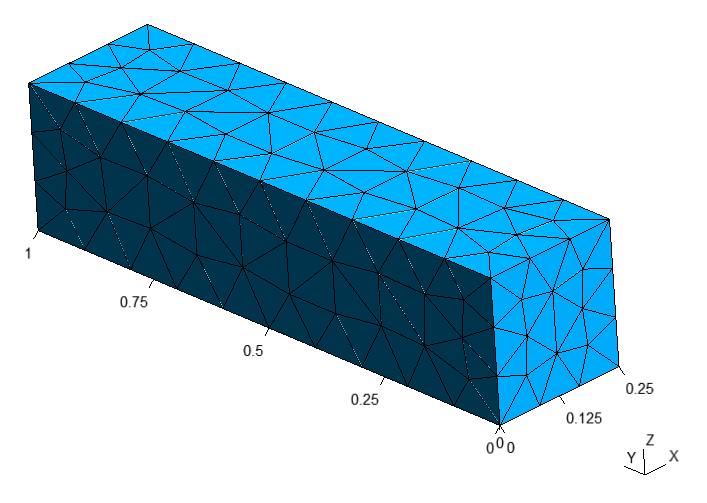
python -m gmsh_scripts bottom.yaml

Structured tetrahedral mesh of the BOTTOM block
One could disable structured mesh generation by setting items_do_structure_map to
0 (1 by default) in the data field:
 1metadata:
 2   run:
 3     factory: geo
 4     strategy:
 5       class: strategy.NoBoolean
 6
 7data:
 8  class: block.Matrix
 9  matrix: [ [ 0;0.01, 0.250;0.1;4 ], [ 0;0.01, 1;0.1;8 ], [ 0;0.01, 0.250;0.1;16 ] ]
10  items_do_structure_map: 0

Unstructured tetrahedral mesh of the BOTTOM block with items_do_structure_map = 0
To create structured tetrahedral mesh with all blocks one should set third parameter in
each of the blocks and run main.yaml
Warning
Number of nodes MUST be consistent between adjacent blocks, e.g. all TOP
blocks should have the same number of nodes by Y and Z axis
top_1.yaml
1 data:
2   class: block.Matrix
3   matrix: [ [ 0, 0.250;0.1;8 ], [ 0, 1;0.1;8 ], [ 0, 0.250;0.1;8 ] ]
top_2.yaml
1  data:
2    class: block.Matrix
3    matrix: [ [ 0, 0.220;0.1;8 ], [ 0, 1;0.1;8 ], [ 0, 0.250;0.1;8 ] ]
top_3.yaml
1 data:
2   class: block.Matrix
3   matrix: [ [ 0, 0.030;0.1;8 ], [ 0, 1;0.1;8 ], [ 0, 0.250;0.1;8 ] ]
bottom.yaml
1 data:
2   class: block.Matrix
3   matrix: [ [ 0, 0.250;0.1;8 ], [ 0, 1;0.1;8 ], [ 0, 0.250;0.1;8 ] ]
python -m gmsh_scripts main.yaml

Structured tetrahedral mesh
To disable generation of structured mesh for all blocks at once one should set
children_items_do_structure_map = [0, ..., number of children] at parent block,
e.g. for main.yaml:
 1 metadata:
 2   run:
 3     factory: geo
 4     strategy:
 5       class: strategy.NoBoolean
 6 data:
 7   class: block.Block
 8   do_register: 0
 9   children: [
10     /bottom.yaml,
11     /top_1.yaml,
12     /top_2.yaml,
13     /top_3.yaml
14   ]
15   children_transforms: [
16     [ ],
17     [ [ 0, 0, 0.250 ] ],
18     [ [ 0.250, 0, 0.250 ] ],
19     [ [ 0.470, 0, 0.250 ] ]
20   ]
21   children_items_do_structure_map: [0, 0, 0, 0]

Structured tetrahedral mesh with disabled children_items_do_structure_map
Structured Hexahedral
For creating structured hexahedral mesh one could do the same steps as for
Structured Tetrahedral but with items_do_quadrate_map = 1 (0 by default)
in the data field:
 1metadata:
 2   run:
 3     factory: geo
 4     strategy:
 5       class: strategy.NoBoolean
 6
 7data:
 8  class: block.Matrix
 9  matrix: [ [ 0;0.01, 0.250;0.1;4 ], [ 0;0.01, 1;0.1;8 ], [ 0;0.01, 0.250;0.1;16 ] ]
10  items_do_quadrate_map: 1
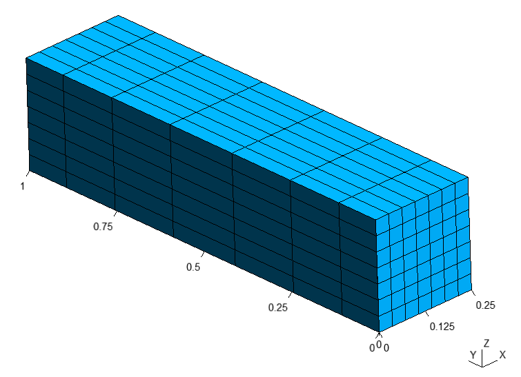
python -m gmsh_scripts bottom.yaml

Structured hexahedral mesh of the BOTTOM block
One could change positions of nodes along axes using one of the two methods:
progression- increase/decrease space between nodes from start point to end pointbump- increase/decrease space between node from center to points
To use progression we should specify 2 additional sub-parameters to the third
parameter separated by ::
The first one is
0(which chooseprogressiontype)The second is a coefficient of the
progression- if coefficient > 1 space will be increasing from first point to second else decreasing
For example, progression sub-parameters 0:1.5 for Y-axis:
 1metadata:
 2   run:
 3     factory: geo
 4     strategy:
 5       class: strategy.NoBoolean
 6
 7data:
 8  class: block.Matrix
 9  matrix: [ [ 0;0.01, 0.250;0.1;4 ], [ 0;0.01, 1;0.1;8:0:1.5 ], [ 0;0.01, 0.250;0.1;16 ] ]
10  items_do_quadrate_map: 1

Structured hexahedral mesh with progression = 1.5
For example, progression sub-parameters 0:0.75 for Y-axis:
 1metadata:
 2   run:
 3     factory: geo
 4     strategy:
 5       class: strategy.NoBoolean
 6
 7data:
 8  class: block.Matrix
 9  matrix: [ [ 0;0.01, 0.250;0.1;4 ], [ 0;0.01, 1;0.1;8:0:0.75 ], [ 0;0.01, 0.250;0.1;16 ] ]
10  items_do_quadrate_map: 1

Structured hexahedral mesh with progression = 0.75
To use bump we should specify 2 additional sub-parameters to the third parameter
separated by ::
The first one is
1(which choosebumptype)The second is a coefficient of the
bump- if coefficient > 1 space will be increasing from the center else decreasing
For example, bump sub-parameters 1:2.0 for Y-axis:
 1metadata:
 2   run:
 3     factory: geo
 4     strategy:
 5       class: strategy.NoBoolean
 6
 7data:
 8  class: block.Matrix
 9  matrix: [ [ 0;0.01, 0.250;0.1;4 ], [ 0;0.01, 1;0.1;8:1:2.0 ], [ 0;0.01, 0.250;0.1;16 ] ]
10  items_do_quadrate_map: 1

Structured hexahedral mesh with bump = 2.0
For example, bump sub-parameters 1:0.5 for Y-axis:
 1metadata:
 2   run:
 3     factory: geo
 4     strategy:
 5       class: strategy.NoBoolean
 6
 7data:
 8  class: block.Matrix
 9  matrix: [ [ 0;0.01, 0.250;0.1;4 ], [ 0;0.01, 1;0.1;8:1:0.5 ], [ 0;0.01, 0.250;0.1;16 ] ]
10  items_do_quadrate_map: 1
Structured hexahedral mesh with bump = 0.5
To generate structured hexahedral mesh of all blocks one could set
items_do_quadrate_map = 0 at each of the blocks or set
children_items_do_quadrate_map = [0, ..., number of children] at parent block,
e.g. for main.yaml:
 1 metadata:
 2   run:
 3     factory: geo
 4     strategy:
 5       class: strategy.NoBoolean
 6 data:
 7   class: block.Block
 8   do_register: 0
 9   children: [
10     /bottom.yaml,
11     /top_1.yaml,
12     /top_2.yaml,
13     /top_3.yaml
14   ]
15   children_transforms: [
16     [ ],
17     [ [ 0, 0, 0.250 ] ],
18     [ [ 0.250, 0, 0.250 ] ],
19     [ [ 0.470, 0, 0.250 ] ]
20   ]
21   children_items_do_quadrate_map: [1, 1, 1, 1]
python -m gmsh_scripts main.yaml

Structured hexahedral mesh
Zones
If we want to add names to entities of the mesh (e.g. volumes of surfaces) we should set
additional field items_zones in the data field
For example, we can add [ [ Volume, [ NX, X, NY, Y, NZ, Z ] ] ]
in the``bottom.yaml``, where:
Volume- volume name[ NX, X, NY, Y, NZ, Z ]- surfaces names:NX- surface pointing in the opposite direction of X-axisX- surface pointing in the direction of X-axisNY- surface pointing in the opposite direction of Y-axisY- surface pointing in the direction of Y-axisNZ- surface pointing in the opposite direction of Z-axisZ- surface pointing in the direction of Z-axis
 1metadata:
 2   run:
 3     factory: geo
 4     strategy:
 5       class: strategy.NoBoolean
 6
 7data:
 8  class: block.Matrix
 9  matrix: [ [ 0;0.01, 0.250;0.1;4 ], [ 0;0.01, 1;0.1;8 ], [ 0;0.01, 0.250;0.1;16 ] ]
10  items_zone: [ [ Volume, [ NX, X, NY, Y, NZ, Z ] ] ]
11  items_do_quadrate_map: 1

Structured hexahedral with zones
Result
Note
We should define different zone names of bottom surfaces of TOP2 and TOP3,
e.g. Top2NZ and Top3NZ respectively
top_1.yaml
1data:
2  class: block.Matrix
3  matrix: [ [ 0;0.1, 0.250;0.1;8 ], [ 0;0.1, 1;0.1;8 ], [ 0;0.1, 0.250;0.1;8 ] ]
4  items_zone: [ [ Volume, [ NX, X, NY, Y, NZ, Z ] ] ]
top_2.yaml
1data:
2  class: block.Matrix
3  matrix: [ [ 0;0.1, 0.220;0.1;8 ], [ 0;0.1, 1;0.1;8 ], [ 0;.1, 0.250;0.1;8 ] ]
4  items_zone: [ [ Volume, [ NX, X, NY, Y, Top2NZ, Z ] ] ]
top_3.yaml
1data:
2  class: block.Matrix
3  matrix: [ [ 0;0.1, 0.030;0.1;8 ], [ 0;0.1, 1;0.1;8 ], [ 0;.1, 0.250;0.1;8 ] ]
4  items_zone: [ [ Volume, [ NX, X, NY, Y, Top3NZ, Z ] ] ]
bottom.yaml
1data:
2  class: block.Matrix
3  matrix: [ [ 0;.1, 0.250;.1;8 ], [ 0;.1, 1;.1;8 ], [ 0;.1, 0.250;.1;8 ] ]
4  items_zone: [ [ Volume, [ NX, X, NY, Y, NZ, Z ] ] ]
main.yaml
 1metadata:
 2  run:
 3    factory: geo
 4    strategy:
 5      class: strategy.NoBoolean
 6data:
 7  class: block.Block
 8  do_register: 0
 9  children: [
10    /bottom.yaml,
11    /top_1.yaml,
12    /top_2.yaml,
13    /top_3.yaml
14  ]
15  children_transforms: [
16    [ ],
17    [ [ 0, 0, 0.250 ] ],
18    [ [ 0.250, 0, 0.250 ] ],
19    [ [ 0.470, 0, 0.250 ] ]
20  ]
21  children_items_do_quadrate_map: [ 1, 1, 1, 1 ]
22  children_items_do_structure_map: [ 1, 1, 1, 1 ]
python -m gmsh_scripts main.yaml

Mesh